

Technical Blog:
Torque. Under New Management.
In days gone by, our engines just had a cable operated throttle plate and that throttle plates position dictated how much power our engines made. Then we added forced induction and things got a little bit more complex, but it was still all about how much air was moved in relation to our foot position.
Nowadays our foot is not connected to the engine at all, the throttle plate itself is electronic, connected only to wires and the driver no has the ability to truly dictates exactly what the engine does. He simply makes a request with his right foot, known electronically as the "Drivers Wish".
Now many of you will know all that, but did you know that your foot actually asks for a very specific torque figure and the ECU will endeavour to provide exactly that torque figure to the flywheel? If you want to learn how it does that, read on...
The Modern Torque modelled ECU.
So, throttle cables are long gone. You have probably all heard of fly by wire in some form or other and that’s how we drive too, by wires and complex electronic signals. What we have now is a pedal connected to an ECU that contains a very complex model of our engine and all its subsidiary systems. To give you a small hint as to how complex, the mere alternator, used for charging our vehicle batteries, now has over 100 tables, switch-points and interesting subsystems just to keep tight control of what it can and cannot do.
The torque request starts with you...
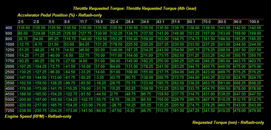
When you put your foot to any given pedal position, you are sending an electrical signal to the ECU which in response references a table known as the "Drivers Wish" or "Driver Demand" that simply tells the ECU that you, the driver, are now demanding a certain torque value. That table references RPM Vs Accelerator pedal position and outputs an answer in Newton Meters. (Nm)
That request from you is then processed by 5 very distinct ECU sub-systems:
- Checks are made to ensure that this torque request isn't higher than other systems are allowing at that moment.
- That torque figure is then punched into a very complex and accurate model to determine exactly how much air load is required to create that amount of crankshaft torque.
- The resulting air load value is then punched into another model to find out how much air mass is required to create that air load.
- The required air mass result is then punched into another model to determine how much manifold pressure is required to get that much air mass inside the engines cylinders given the current air density.
- That manifold pressure desired is fired through to the turbocharger model to determine the required turbine speed and waste-gate position to create that manifold pressure with the compressor.
Once the answers are all known, the ECU supplies that air load and whatever fuel and spark is required. The whole process is over in microseconds! Now the above is dumbed right down to make it sound simple. Each step of this process is exponentially more complex than I have described, but now we have outlined it i think we can dive in and look at each step in a little more detail.
Step 1: Check the drivers torque request against limiters.
Let's look at the above driver demand table and choose full throttle at 4000 RPM. We can see that the driver demand there is 678 Nm of torque. The first thing that happens in response to this request is that the ECU cross references all its limiters and safety systems to ensure that torque figure is currently allowed. If there is an external limit in place lower than that, then the ECU will cancel that commanded 678NM and replace it with the lowest of those torque request limiters.
Torque Request Limiters? Such as... ?
The torque request limiter tables are too numerous to mention but include a few such things as:
- Gear ratio limiters: These limiters give us different torque limits in each gear. (For traction normally).
- Gearset limiters: These are limits to protect the gearbox itself.
- Steering angle: Full power is often only allowed within a few degrees of centre.
- Rain sensor: Some ECU's run torque limits based on current detected rain levels.
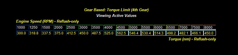
If any of those systems are currently indicating a torque ceiling that is lower than the driver demand table, they will take precedence immediately and become the torque source. Example below of a 4th gear limiter:
Step 2: Convert that torque request into an air load.
So let's assume the torque request has come out at 525 Nm of torque at 4000 RPM due to that gearbox limiter above. Where do we go from here?
Well let's remember that torque is
produced by applying load to a crankshaft via the combustion of fuel and air in the cylinders. The
more air and fuel we process, the more load we create on the piston crown and the harder we drive the crankshaft round.
The ECU's job is to respond to our torque request by delivering the perfect amount of fuel/air mix, and thus load. To do this, the ECU has a model to refer to that is directly related to the engines volumetric efficiency. From there it can look at the air pumping capacity of the engine as an “Air load” and this load is converted to a pretty simple numeric format that outputs numbers such as "1.0".
To very briefly describe air load... a load of 1 is essentially the cubic capacity of the cylinder. So if we manage to cram 500cc of air into a 500cc cylinder we have achieved a volumetric efficiency of 100%. We call this a load of 1.0.
Turbo-charging of course allows us to fit more oxygen into the same 500cc and allows loads of over 100%, but that is more complex than it first seems as of course we still only physically have a 500cc cylinder, but filling that 500cc cylinder with air under pressure packs in more oxygen to the same space... That’s a topic for another blog, but suffice to say that the ECU has a complex model programmed into it that allows it to understand precisely how much air load is generated by the pressurised air and conversely, how much air is required in the cylinder to create a given Nm of torque figure.
Again, these systems all rely on complex models created from the ground up by the engineers and much of that data is represented by ECU tables internally. There are a great many of these air load tables (32 in the latest Fords for example) and they have an identical number of sanity check tables that work in reverse, working out Air load to torque instead of torque to air load, so make that 64 load tables in a 2018 Ford EcoBoost The reason for all those tables is the ECU has this data modelled accurately across any number of camshaft timing variations to take account of modern VVT systems. Variable valve lift such as found on the latest cam-less BMW systems add even more levels of complexities to this side of the calculation.
Are there any limiters? You bet... Air load usually has the most limiters!
The air load limiter tables are again too numerous to mention but include a few such things as:
- Cylinder pressure limits. For power limitation, gasket integrity etc.
- Detonation limiters: The biggest cause of knock is cylinder pressure.
- Low octane load limits: As above, low octane means lower load limits.
- Combustion stability: In order to control LSPI, there are limits to how much load we can generate low down.
If any of those systems are currently indicating an air load ceiling that is lower than the torque creation demands, they will take precedence immediately and become the air load source.
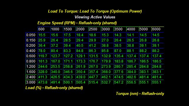
But for today’s example, let's assume we have decided on an unchallenged air load for 525NM of 2.60 which you can see in the table below. The ECU interpolates the figures between all cells of course, but you want to be looking at the 4000 RPM column and aiming to obtain an air load for 525NM as dictated by the 4th gear limiter we mentioned earlier. Let's round it off here to 2.60.
Example of an air load table.
Step 3: Convert that air load into air flow.
So we know that we need a load of 2.60 to generate the requested 525 Nm of torque, but how much air is that in an air pump (engine) that is processing hundreds of these cylinder fills per second?
Well again, thanks to a complex model built up by the development engineers, the ECU knows precisely how well the engine flows air in any given scenario, with any given cam position and any given throttle opening as it knows the volume of every pipe, the manifold, the intercooler, everything. So it can calculate based on the current air density just how much air must be moved through the engine per second to fulfil the requested air load. This air flow is measured in Kg/min.
Again, many air flow limiters are checked to ensure the required number is acceptable. Limiters such as:
- Compressor airflow limit: Dictated by the turbo manufacturer for safe reliable operation.
- Turbine airflow limit. (As above)
- Injection pulse width limit: Can we supply enough fuel for this much air?
Step 4: Convert that air flow into air pressure.
So now we know that we need to supply air at the rate of let's say, 14 Kg/min to achieve our target air load of 2.60 which in turn when combusted will give us our requested target of 525 Nm.
But how do we put 14 Kg/min of air into the cylinder?
The answer, is with some pressure... So this subsystem now refers to its complex MAP (Manifold Absolute Pressure) Vs air flow model and determines how much manifold pressure is needed to put exactly that volume of air in the cylinder given the current requested cam timing and the engines volumetric efficiency at this point.
As always, there are nanny's in place whom can overrule our boost creation fun!
- Compressor outlet limit: Is the compressor allowed to create that boost?
- Compressor speed limit: Is the compressor allowed to go that fast?
- Manifold pressure limit: Is the engine allowed to see this much boost?
Those are just three examples of the many... So let's for ease of discussion just assume that all is well and that pressure turns out to be 20psi. That is the 14 Kg/min air flow request taken care of by converting it to boost.
Step 5: Deliver that air pressure.
This side of things is now far more complex than it used to be. On the turbine side, in days gone by we had an actuator canister that just opened at a set pressure and diverted gas away from the turbine at a given pressure. Technically, this is still the case, however, nowadays the ECU is now modelling the turbine operation in BTU's (British Thermal Units - A measure of heat) . The ECU is actually calculating the amount of heat energy required to spin the turbine to speed and deliver the required inlet pressure via the compressor. It even models precisely the ratio of exhaust gas that must be bypassed to waste through the waste-gate.
On the compressor side, it is well worth noting that the system controls TIP (Throttle Inlet Pressure) and MAP (Manifold Absolute Pressure) as two separate but intrinsically linked mechanisms. TIP is controlled by the waste-gate, and MAP by the throttle blade.
The waste-gate controls the pressure in the inlet (TIP) and the throttle is then used almost like a tap on a hosepipe to feed the pressure from the inlet into the manifold at the required pressure (MAP). This is one of the strategies that has led to the almost instantaneous response of modern turbocharged engines. We no longer have to wait for boost to spool, it is often already there but being kept in check by a throttle valve.
On that note, it is also interesting to observe that while your foot is mashed into the carpet, the ECU is often opening and closing the throttle to control the manifold pressure whilst the waste-gate is being controlled in order to supply inlet pressure.
Any Limits? Well, its boost, so of course there are many limits in place...
There are a huge amount of boost limits as you can imagine, so I won't bullet point these, but there are boost limits for different gears, master boost limits, RPM boost limits, over-boost timers and even boost creation speed limits (how fast it is allowed to make the boost)

The job is almost done...
Everything is calculated out now, but this blog has of course been massively simplified for easy digestion.
There are a huge array of other limits that govern all of the above processes as a kind of over-watch system:
A brief rundown of just a few of the common limiters active in almost every ECU out there:
- Engine knock: Load can be reduced due to knock... See blog here.
- Exhaust gas temperature: Load is often reduced to allow exhaust cooling.
- Coolant temperature: Load is limited in overheat situations.
- Gearbox temperature: Load is limited by gearbox oil temperatures.
- Differential temperature: Load is limited by diff oil temperatures.
- Clutch temperature: Load is limited by clutch-pack temperatures.
- Inlet air temperature: Boost can be raised or lowered by air temperatures.
- Brake rotor temperature: Load is often limited with very hot brake rotors.
So what did we learn?
In today’s brief example, the driver asked for 625 Nm, the gearbox said no you can't have it, the max you are allowed is 525 Nm, the ECU worked out it needed an air load in the cylinder of 2.60 and then went on to determine that 14 Kg/min of airflow was needed to achieve that load and that to move that much air it was going to have to pressurise the manifold to 20psi to achieve it.
From there it determined how many BTU's (British Thermal Unit) of heat to process through the turbine to supply the boost, directed some air to the waste-gate to regulate that, checked the exhaust gas temp, cylinder head flange temp and catalyst temps were going to stay within limits and started to create the necessary throttle inlet pressure to the throttle so that it, in turn could regulate the manifold pressure to 20psi.
In essence we still just
pumped in the air, added some fuel, compressed and lit the mixture and pushed the piston down... but now, thanks to ECU control we generated exactly 525 Nm on the button. Simple eh?
Far from It...
Hopefully you now have some idea of how the modern torque modelled ECU is more complex than this brief outline can ever explain. Indeed the ECU technical document itself is well over 8000 pages but what you have just read above is a good outline to get you into it.
It is worth me mentioning that all of the above is modelled via a theoretically perfect air/fuel ratio and spark table and modified according to how far from those numbers the engine currently has to run. It also has models that inform it how much torque is lost through other components such as air conditioning, alternator, water pump and even the torque loss due to drag from the engine oil.
The ECU can and will swap boost for spark when it thinks it is more suitable, or run more spark to combust a slower burning AFR or run less boost pressure when the air is cold and dense and indeed more boost pressure when the air is hot and its density is lower. It has all bases covered.
Further Reading...
If you are interested to read a little more about how the system infers a fuel octane, or how these systems are modelled in actual Nm of torque and convert your torque request into air loads, you will find some of my other Ecoboost blogs tie in very nicely with the one you have just read.

Author:
Stewart Sanderson - June 11th 2018